555 Timer Circuit with 50% Duty Cycle
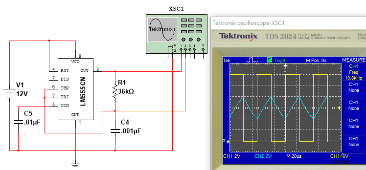
Figure 1 - 50% Duty Cycle 555 Timer
This circuit provides a 20kHz output with a 50% duty cycle.
Design Details -- How it Works
From the datasheet for the LM555 Timer, the output pin (pin 3) of the timer will transition to high
when the voltage on the trigger pin (pin 2) falls to $\frac{1}{3}V_{CC}$, and will transition to low when the voltage on the threshold pin (pin 6)
rises to $\frac{2}{3}V_{CC}$. This behavior is illustrated in the scope traces above where the yellow trace is the 555 timer pin 3 output and the blue
trace is the voltage across the timing capacitor $C_4$. From the scope trace, with the timer output high, the voltage across the timing capacitor rises
from 4V (i.e., $\frac{1}{3}V_{CC}$) to 8V (i.e., $\frac{2}{3}V_{CC}$) at which point the timer output transitions to low. With the timer output low, the timing
capacitor begins to discharge from 8V (again, $\frac{2}{3}V_{CC}$) down to 4V, which places $\frac{1}{3}V_{CC}$ on the trigger pin causing the output to
transition to high. This process repeats, resulting in a 50% duty cycle waveform.
The equation we will utilize to analyze the 555 timer circuit above corresponds to the solution of the first-order differential equation (FODE)
(in standard form) that arises from a KVL analysis of an RC circuit. Although we only need said equation representing the solution, I will briefly go through
its derivation for completeness (you can skip this section if desired.)
Consider the RC circuit below:
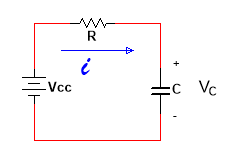
The KVL equation is: $iR + v_c(t) - v_{cc} = 0 \text{ where } i=C\frac{dv}{dt}$. Substituting for $i$ and rearranging yields:
$$-v_{cc} + RC\frac{dv}{dt} + v_c(t) = 0$$
Dividing through by RC and rearranging: $$\frac{dv}{dt} + \frac{1}{RC}v_c(t) = \frac{1}{RC}v_{cc}$$
Which in standard form becomes
$$\frac{dv}{dt}+\frac{1}{\tau}v_c(t) = K \text{ where }\tau=RC, v_{cc}=K\tau$$
For $y \ge 0$, the solution to the above DE is: $$v_c(t) = K\tau + [v_c(0) - K\tau]e^\frac{-t}{\tau}$$
In the above equation, $v_c(0)$ is the initial DC voltage on the capacitor and $K\tau$ is the steady-state DC voltage (or final voltage).
From this we get the familiar charging equation: $$v_c(t) = v_{cc} + [0 - v_{cc}]e^\frac{-t}{\tau} = V_{cc}[1 - e^\frac{-t}{\tau}]$$
and discharging equation $$v_c(t) = 0 + [v_{cc} - 0]e^\frac{-t}{\tau} = v_{cc}e^\frac{-t}{\tau}$$
For this analysis, we will represent the charge on the capacitor at time $t$ as $$v_c(t) = v_f + [v_i - v_f]e^\frac{-t}{\tau}$$
where $\tau = RC$, $v_f$ is the steady state (or final) voltage across the capacitor, and $v_i$ is the initial voltage across the capacitor.
Note that steady-state will refer to the final voltage across the capacitor if we allow sufficient time for the capacitor to charge (or discharge); so,
if we are charging the capacitor with a voltage of $v_{cc}$,
then the steady-state voltage across the capacitor would be $v_{cc}$ volts. Similarly, if we are discharging the capacitor to ground, then the
steady-state voltage across the capacitor would be 0 volts.
Refering to the waveforms in Figure 1 above, when power is first applied to the 555 timer chip, its output (pin 3) will be high (i.e., $v_{cc}$),
and $C_4$ will begin to charge through $R_1$ until the voltage across $C_4=\frac{2}{3}v_{cc}$. Since this voltage is present on the threshold input
(pin 6), the timer's output will transition to low (i.e., 0 volts). Let's begin the analysis at this point. (For reference, we are at the first vertical
trace from the left.)
We want to show that the circuit's output waveform is high 50% of the time and low 50% of the time (by definition of a 50% duty cycle). Let $t_H$ denote
the time the output is high, and $t_L$ denote the time the output is low. Then, for a 50% duty cycle, we need to show $t_H = t_L$.
At our established reference point on the waveforms, $v_c(t) = \frac{2}{3}v_{cc}$ and the timer's output is low. Per previous discussions, we know that
the timer's output will transition to high when $v_c(t) = \frac{1}{3}v_{cc}$. To determine how long the timer's output will remain low, we need to solve
for $t$ in our capacitor charge equation $$v_c(t) = v_f + [v_i - v_f]e^\frac{-t}{\tau}$$ where $v_c(t) = \frac{1}{3}v_{cc}$, $v_i = \frac{2}{3}v_{cc}$,
and $v_f = 0$ (we are discarging
the capacitor; so, the steady-state value would be zero volts.) Substituting these values yields
$$\frac{1}{3}v_{cc} = 0 + [\frac{2}{3}v_{cc} - 0]e^\frac{-t}{\tau} \text{ or } \frac{1}{3}V_{cc} = \frac{2}{3}v_{cc}e^\frac{-t}{\tau}$$
Simplifying gives $$.5 = e^\frac{-t}{\tau}$$ and taking the natural logarithm of both sides gives
$$ln(.5) = ln(e^\frac{-t}{\tau}) \text{ or } -.693 = \frac{-t}{\tau}$$. Finally, solving for $t$ we get $$t_L = t = .693\tau$$
At this point, the timer's output is high and the voltage across the capacitor is $\frac{1}{3}v_{cc}$. To determine how long the timer's output will
remain high, we again solve the capacitor charge equation, but this time $v_c(t) = \frac{2}{3}v_{cc}$ (because the output will transition low
when the voltage on the threshold pin reaches $\frac{2}{3}v_{cc}$) , $v_i = \frac{1}{3}v_{cc}$,
and $v_f = v_{cc}$ (we are charging the capacitor this time; so, the steady-state voltage would be $v_{cc}$ volts.) Substituting these values yields
$$\frac{2}{3}v_{cc} = v_{cc} + [\frac{1}{3}v_{cc} - v_{cc}]e^\frac{-t}{\tau} \text{ or } \frac{2}{3}v_{cc} = v_{cc}[1 - \frac{2}{3}e^\frac{-t}{\tau}]$$
Simplifying (i.e., dividing both sides by $v_{cc}$ and subtracting 1 from both sides) gives $$-\frac{1}{3} = -\frac{2}{3}e^\frac{-t}{\tau} \text{ or }
.5 = e^\frac{-t}{\tau}$$ As before, we take the natural logarithm of both sides and solve for $t$ yielding $$t_H = t = .693\tau$$
In the preceeding analysis we have shown that $t_L = t_H$; so, our circuit does indeed provide a 50% duty cycle output. Finally, since frequency is
equal to the inverse of the period, we have the frequency of oscillation of our circuit as
$$f = \frac{1}{t_L+t_H} = \frac{1}{2(.693)\tau}$$
which is $20kHz$ for the circuit in Figure 1.